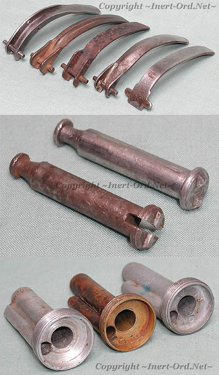
A selection of safety lever types, from an early pierced type to the flat stamped No.36.
The first design required custom drilling to match the corresponding holes in the grenade body it was intended for. Often levers are not interchangeable between different manufacturers. This was soon changed in favor of placing the safety pin over the lever, eliminating the lever holes.
With the advent of the No.23 Mk.III grenade the lever was simplified to a curved flat stamping.
Strikers
The striker was originally a solid part but was soon found to hinder adequate air flow for the burning fuze, so a vent slot was added to allow combustion gases to escape. This was an early No.5 change.
Centrepiece
Centrepieces were made of different materials as well as using different manufacturing techniques.
An early aluminum cast piece is shown at left.
At center is a fabricated brass assembly consisting of a threaded base with separate detonator and center tubes, joint to make a single unit.
On the right is another cast part, made from zinc alloy, with a stamped "Z" and date. This is typical of WWII production.
